
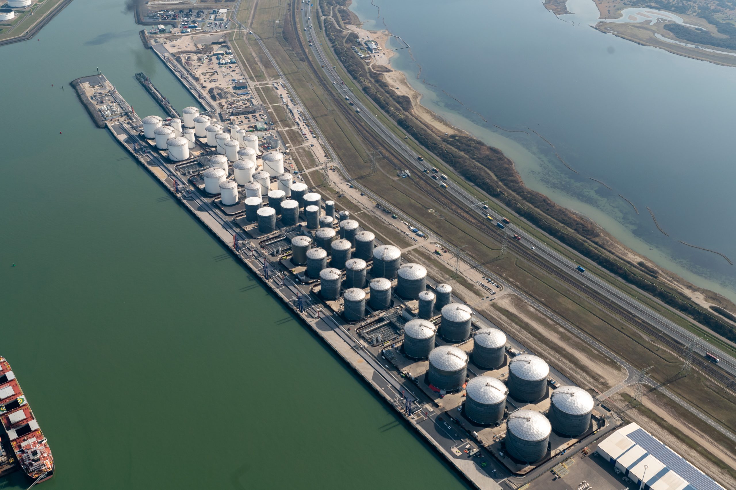
The brand new HES Hartel Tank Terminal has been developed at Maasvlakte in the Port of Rotterdam, the Netherlands. Maasvlakte is a massive manmade westward extension of the Europoort port and industrial facility within the Port of Rotterdam, built on land reclaimed from the North Sea.
The tank terminal is constructed on a 27 ha site in the strategically located Maasvlakte area. It offers 1.3 million m3 of storage capacity for clean petroleum products (gasoline, diesel, gasoil, and jet fuel) and biofuels. It is specifically designed for blending and mixing operations.
Maasvlakte is an excellent location for a liquid bulk terminal, offering a very large crude carrier (VLCC) draught terminal with direct sea access. The 1.2 km quay has a draught up to 23.6 m and offers six mooring positions for sea-going vessels. The nine barge positions provide excellent opportunities for shipments to the European hinterland. Furthermore high tech subsea pipelines connect the terminal to a neighbouring refinery. The terminal complies with the highest safety and environmental standards and has a strong and proactive focus on sustainability.
To comply with environmental permits for volatile organic compound (VOC) emissions associated with filling of sea-going vessels and barges, as well as storage tank filling, a vapour treatment system (VTS) was required. John Zink (JZ) provided an integrated design and was awarded the contract for design, delivery, installation, commissioning and start-up.
VTS DESIGN
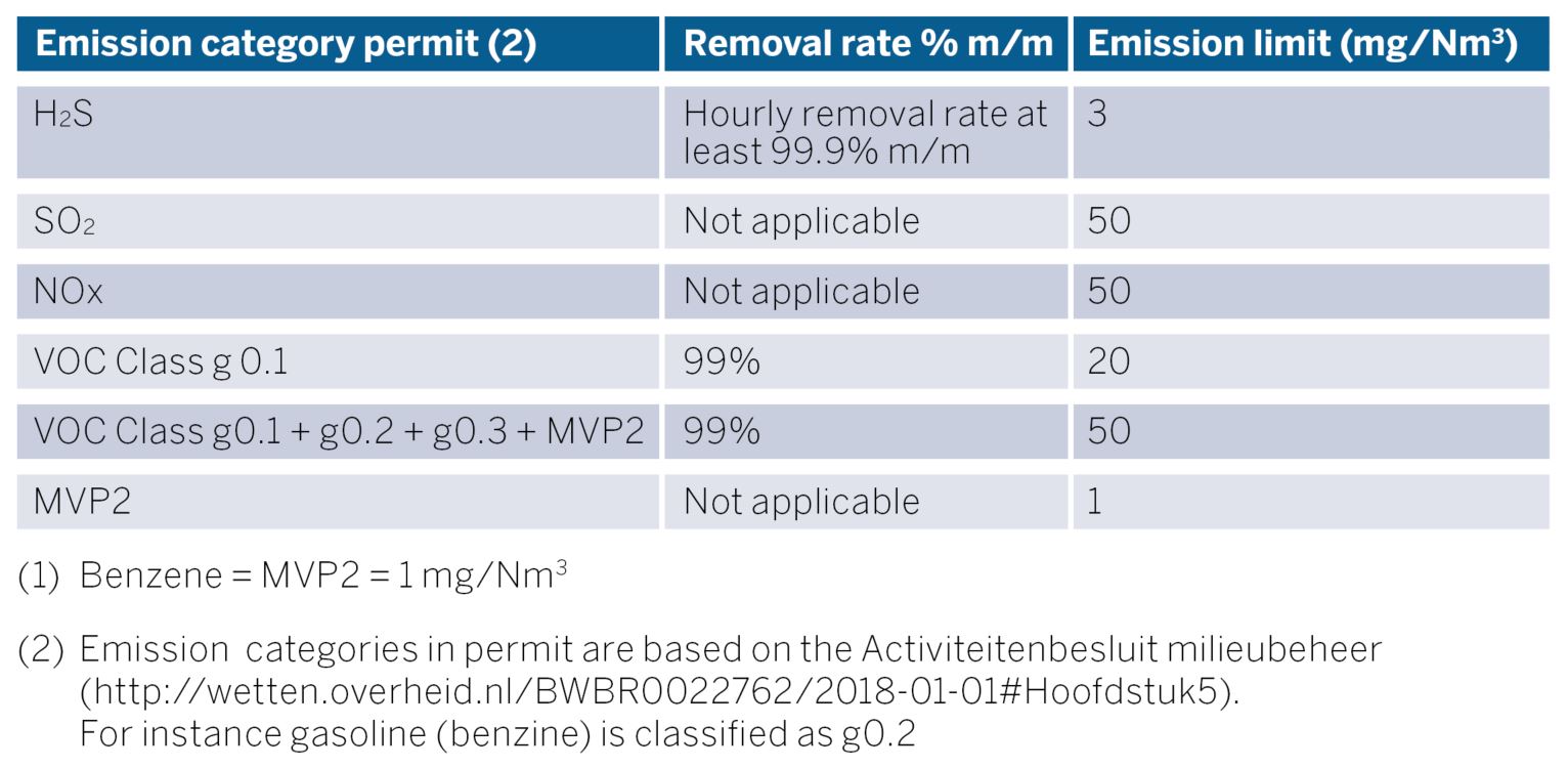
The VOC recovery rate for VTS was specified as minimum 99% of the inlet concentration in combination with very low emission concentrations. The VOC emission limits in the table in Figure 1 are inclusive of methane and ethane. As recovery of these is a challenge for an activated carbon vapour recovery unit (VRU), a two-stage technology was developed and offered as an integrated VTS.
In view of defined 8,000 m3/hr continuous liquid loading capacity, redundancy requirements and energy saving ambitions, JZ designed two parallel VTS trains of 4,000 m3/hr each. The VTS treats Zone 0 mixtures including but not limited to mixtures of vapours of organic compounds, nitrogen and inert gas (flue gas) as well as treating sulphur compounds which may be present from previous cargoes. Products and composition change depending on market demand, which makes VTS flexibility an important design criterium. The VTS is also designed to efficiently remove H2S, mercaptans, and other sulphuric compounds from the vapour.
Expected products to be loaded are diesel, gasoil, gasoline, and high benzene-containing blend components such as:
- Summer and winter gasoline;
- Gasoline blend products with pygas containing up to 50% benzene
- Gasoil (high and low sulphur)
- Diesel (high and low sulphur)
Each VTS train consists of a first stage VRU and a second stage regenerative thermal oxidiser (RTO) complete with programmable logic controller (PLC) controls, motor control centre (MCC) and analyser equipment.
Worldwide there are very few VRUs upgraded with a second stage, and the delivery of two integrated two-stage technology VTS is quite unique with challenges in view of capacity and system control. It is expected that in general, future EU, national or local emission requirements will become more stringent and it is anticipated that this project will be a future benchmark reference in the vapour control industry.
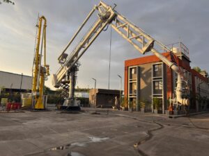
In addition to system design, fabrication and delivery, site mechanical and electrical installation works were included in the scope of the work. The vessels were delivered by barge to the installation site and lifted in place direct from barge onto their foundations.
RTOs were delivered in modules by road and lifted in position followed by the VRU skids, platforms and piping to complete the VTS. VTS train installation commenced mid-February 2021 with lifting completed within six weeks due to proper scheduling of deliveries and activities between HES and the JZ site supervisor and project manager. Following lifting, the JZ site erection teams finished installation of pipe work, installation of JZ-supplied control buildings, electrical and instrumentation (E&I) works over a period of four months. During Q3 2021, site welding activities were performed to connect VTS interface piping to site vapour header, absorbent and nitrogen.
VRU TECHNOLOGY
The high-efficiency hydrocarbon vapour recovery system (Figure 2) consists of two trains capable of processing 100% design flow rate, i.e. 8,000 m3/hr liquid loading rate. Each VRU unit is equipped with two identical adsorbers filled with activated carbon. One adsorber vessel is on-stream receiving vapours in the adsorption mode while the other vessel is off-stream in the regeneration mode. Switching valves are provided to automatically alternate the adsorbers between adsorption and regeneration, on a time-cycle basis, so that one adsorber set is always on-stream, thus assuring uninterrupted vapour processing capability.
Due to the high amount of H2S in inlet vapours, a sacrificial sulphur guard bed is installed at the inlet of each VRU. The hydrocarbon vapour-air mixture to be processed flows up through the on-stream adsorber vessel. In the adsorber, the activated carbon adsorbs the hydrocarbon vapour and allows clean air to vent from the bed with minimal hydrocarbon content. Carbon bed regeneration is accomplished with a combination of high vacuum and purge air stripping which removes previously adsorbed hydrocarbon vapour from the carbon and restores the carbon’s ability to adsorb vapour.
Liquid ring vacuum pumps (LRVPs) are used as the source of vacuum for carbon regeneration. In addition, vacuum booster blowers (VBBs) are provided to operate upstream and in series with the LRVPs to enhance regeneration efficiency. The VBBs and vacuum pumps extract concentrated hydrocarbon vapour from the carbon bed. The vacuum pumps are operated with a sealing fluid which is a specially blended Z-seal ethylene glycol formulated to enhance the rotating equipment lifetime. From the vacuum pumps the non-condensed hydrocarbon vapours plus hydrocarbon condensate and seal fluid are discharged to a three-phase separator vessel where seal fluid and hydrocarbons get separated. The heat of compression is removed by circulating the seal fluid through a heat exchanger using a partial stream of the absorbent flow as coolant.
From the separator vessel, the vapours flow to a vertical packed absorber column that functions as the recovery device. In the absorber, the hydrocarbon vapour flows up through packing where it is liquefied and subsequently recovered by absorption into a hydrocarbon liquid absorbent. Product from the customer’s storage tank can be utilised as the absorbent. A centrifugal pump circulates the product from the storage tank to the absorber column. In the absorber column, the absorbent absorbs the hydrocarbon-rich vapours from the separator. The recovered liquid and absorbent are then pumped back to the customer return line. A small stream of air and residual vapour exit the top of the absorber column and are recycled to the on-stream carbon bed where the residual hydrocarbon vapour is re-adsorbed.

PRINCIPLE OF RTO TECHNOLOGY
Downstream of the VRUs, two RTOs are installed. VOCs not adsorbed in VRUs are oxidised in RTOs, venting to the atmosphere a stream which complies with customer’s emission requirements. Each RTO has its own PLC to safely and efficiently control the process.
The RTO destroys VOCs discharged from industrial processes. The system achieves VOC destruction through high temperature thermal oxidation, converting the VOCs to carbon dioxide and water vapour, recycling released energy to reduce operating costs. VRU outlet vapours with VOC contaminant are routed to enter the RTO canisters. A flow control valve directs this gas into an energy recovery chamber which preheats the process stream. The process gas and contaminants are progressively heated in the ceramic bed as they move towards the combustion chamber.
The VOCs are then oxidised, releasing energy in the second ceramic bed, thereby reducing any auxiliary fuel requirement. The ceramic bed is heated and the gas is cooled so the outlet gas temperature is only slightly higher than the inlet temperature. While two canisters are in depuration cycle, the third one is in purge mode. The flow control valve switches and alternates the ceramic beds flow direction and sequence over time into inlet, outlet and purge modes.
The VTS is designed in such a way that the VRU emissions contain the correct level of VOCs to allow auto-thermal
RTO operation which greatly reduces energy consumption.
Due to the presence of sulphur compounds a hot by-pass was added to warm-up the inlet vapours above acidic dew point to avoid material selection issues.
SUMMARY
The HES Hartel Maasvlakte Rotterdam project provided a unique opportunity for John Zink Hamworthy Combustion to demonstrate their capabilities to meet the most stringent emission requirements. JZ has supplied over 2,000 vapour control solutions worldwide and this, in combination with its own research centre and laboratories, provides the company with unique know-how and experience to provide standard capacity emission truck loading equipment, as well as large marine installations with large capacities and very stringent emissions. JZ supplies both combustion and vapour recovery equipment as well as two-stage VRU/oxidation technologies. The HES Hartel site is expected to be commissioned in 2022.
‘No significant quality or safety issues were reported during the installation of VTS, which demonstrates the capacity of John Zink to deliver quality projects and provide customer support from design to installation and commissioning,’ says Julien Morel, project manager for John Zink Hamworthy Combustion.
For more information:
www.johnzinkhamworthy.com